Thermoplastic Elastomer Molding Guidelines:
Overmolding Design Considerations
The wall thickness of the substrate and overmold should be as uniform as possible to obtain cycle times. Wall thickness in the range from 0.028 to 0.150 in (0.711 to 3.81 mm) will ensure good bonding in most overmolding applications. If the part requires the use of thick sections, they should be cored out to minimize shrinkage problems and to reduce the part weight and cycle time.
Transitions between wall thicknesses should be gradual to reduce flow problems such as back fills and gas traps. The use of radii, 0.020 in (0.508 mm) minimum, in sharp corners helps reduce localized stress. Deep blind pockets or ribs that are difficult to vent should be avoided. Long draws should have a 3-5° draft to help ejection. Properly designed undercuts however are possible with TPE compounds if the part does not have sharp corners and the elastomer is allowed to deflect during ejection.
Successful Overmolding
- Proper gate size/location
- Vent location(s)
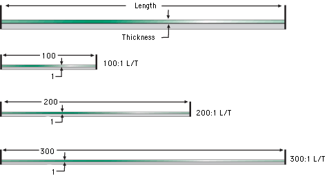
- Maximum flow length (L/T)
- Proper surface texture
- Applicable de-gating/part ejection
- Proper shut off technique(s)
- Use mold filling analysis CAE for appropriate complex geometries
Overmolding Considerations
- Use 0.150 in (3.81 mm) as a guideline for nominal maximum wall thickness.
- Use of mechanical interlocks on thin wall applications.
- Use 0.028-0.032 in (0.711-0.812 mm) as a guideline for absolute minimum wall thickness.
- Do not vary TPE component wall thickness by greater than 4:1.
- Length/thickness greater than 150:1. Thin walls can pose flow challenges and the ability to pack out the component. The flow length to thickness ratio should be 150 maximum. If higher than 150, consider utilizing multiple gates to achieve optimum fill/minimal knit line issues.


