Thermoplastic Elastomer Molding Guidelines:
Overmolding Design Considerations
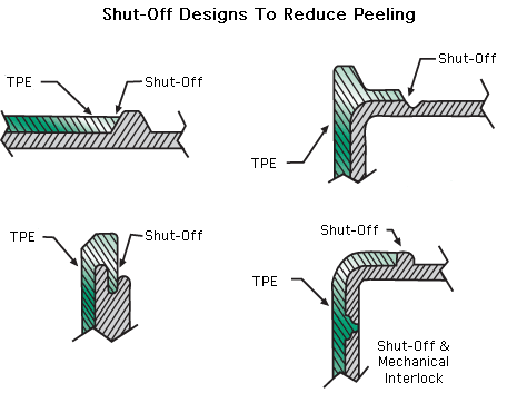
Proper shut off design is critical to stop the TPE flow in precise geometry location and prevent undesirable random edge flash.
Approach for Good Functionality
- Design shut off to minimize potential for edge peeling of TPE
- General geometry needs to be a very sharp transition area between molded TPE edge and supporting substrate.
- Resulting TPE geometry must be designed to vent the cavity properly


Shut-Off Recommendations
- Provide interference fit of 0.002 to 0.004 in (0.050 to 0.101 mm) – somewhat dependant on cosmetic needs
- Specific plastic substrate ductility
- Heat treat shut off steel to a minimum 54 Rockwell hardness
- Consider substrate edge design to “hide” TPE edge from consumer.
- Pre-dry hygroscopic substrate and TPE pellets to avoid porous surfaces nearest substrate interface
- Where appropriate, have the actual shut-offs employed as inserts (helps downstream injection mold maintenance)
Shut-Offs to Avoid
- Avoid using rounded/radiused shut offs
- Component designs where TPE geometry lies high above the substrate (e.g., cliff wall)
- Placing shut offs directly in the mold base
- Building the tool without developing a clear shut off strategy first
- Placing the vent directly at shut off edges – can actually encourage flashing
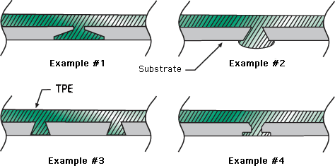
Fundamental “lock” of TPE to Substrate: Three Basic Methods
- Chemical adhesion
- Mechanical design techniques
- Interlocks
Mechanical Interlocks Offer Major User Benefits
- Mechanical combination of TPE/substrate geometry (very difficult to separate in use)
- Method to greatly improve component abrasion resistance
- Can be used across a substrate geometry – multiple locations


